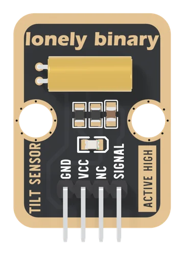
Specifications
| Type | Ball tilt switch with a pull-down and an indicator LED. Left edge down reads HIGH |
|---|---|
| Switch | SW-520D: two steel balls in a brass can, 12 × Ø5 mm, lying flat with its leads at the board's left edge |
| Angle | Closes with the lead end about 10° below level and opens with the other end about 10° below, by one maker's sheet; in between it keeps its last state. Not measured on this block |
| Axis | One: across the board, left edge against right. Tipping the header or top edge down leaves it level |
| SIGNAL | The switch's other end, with a 10 kΩ pull-down and 100 nF to GND. Open: 0 V, LOW. Closed: VCC, HIGH. Read it with INPUT, not INPUT_PULLUP |
| Filtering | The 100 nF hides openings under about 1 ms on a 3.3 V board, 0.5 ms on an Uno. Filter longer rattles in the sketch, 50 ms |
| Supply | Your board's logic voltage on VCC: 3V3 on an ESP32, ESP32-S3 or Pico, 5V on an Uno. A closed switch puts VCC straight on the pin |
| Current | 0 mA while open: VCC reaches only the switch. Closed, about 1.6 mA at 3.3 V and 3.5 mA at 5 V, from VCC, none from your pin. The switch is rated 12 V, 10 mA |
| Indicator | Red LED and 1 kΩ on SIGNAL: lit while the switch is closed, fed through it. Not a power light |
| Pins to wire | 3 of the 4: GND, VCC and SIGNAL. NC is connected to nothing on the board |
| Header | 4-pin right-angle male, 2.54 mm pitch: GND, VCC, NC, SIGNAL, with GND on the square pad |
| Board | 22.4 × 30.4 mm, two 4.8 mm mounting holes 16 mm apart. The front prints ACTIVE HIGH, the back ANGLE DETECTION |
| In the box | 1 × TK62 block. It also ships inside the TinkerBlock kits |
What it does
It tells your board which end of the block is lower. The brass can across the top is a ball tilt switch: two steel balls loose inside, and the switch's contacts at the end with the leads. When that end is the lower one the balls roll onto the contacts and close the switch; when the other end is lower they roll away.
On this board the can lies flat, leads at the left edge, and the switch joins VCC to SIGNAL. A 10 kΩ holds SIGNAL LOW while it is open, so the left edge down reads HIGH, as ACTIVE HIGH on the front says. A 100 nF beside it smooths the shortest flickers, and a red LED on SIGNAL lights while the switch is closed. Open, the block draws no current.
The page this replaces called the resistor a pull-up (it is a pull-down), said it reads HIGH whenever it is tilted (it reads HIGH when one particular edge is down, and either way near level), put the switching angle three times higher than the one sheet that gives an angle, and wired SIGNAL to a Pico's GPIO 0.
Three things to know before wiring
- Only left against right. The can lies across the board. Tipping the header edge or the top edge down leaves it level, and a level can keeps whatever it last read.
- VCC is your board's logic voltage. A closed switch puts VCC straight on your pin: 3V3 on an ESP32, an ESP32-S3 or a Pico, 5V on an Uno.
- Read it with
INPUT. The pull-down is on the board.INPUT_PULLUPfights it, and on an Uno can leave the open level where the pin does not promise to read LOW.
Wiring, in four lines
- GND to your board's GND.
- VCC to 3V3 on an ESP32, ESP32-S3 or Pico; 5V on an Uno.
- SIGNAL to GPIO 4 on an ESP32-S3, GPIO 25 on an ESP32, D2 on an Uno, GP15 on a Pico.
- NC to nothing: it is connected to nothing on the board.
Then pinMode(pin, INPUT), and digitalRead(pin) is HIGH while the left
edge is down.
Where to start
The handbook below is ten short articles, each with a working figure. The first read is the whole build in three wires and a few lines, and counting tips adds the filter a ball switch needs.
For how it works, read two balls in a can and which end is lower. If it reads the wrong thing, when it reads wrong. For four sides at once, the four-direction tilt sensor.
When it doesn’t work
- Which way up reads HIGH?
- Left edge down: the edge the brass can's two leads are at, seen from the front with the header at the bottom. The balls roll to that end and close the switch. Right edge down reads LOW.
- It reads HIGH one time and LOW the next lying flat. Is it broken?
- No. Flat, the can is level, and within about 10 degrees of level the balls stay wherever they last rolled. Level is not a reading on a ball switch. Mount it with one edge clearly down.
- I tip it forwards and nothing happens.
- The can lies across the board, so tipping the header edge or the top edge down only rolls it about its own length. Only the left or right edge going down tilts it.
- At what angle does it switch?
- Bailin's SW-520D sheet says about 10 degrees past level, either way; the sheet from the maker of this board's part gives no angle, and nobody has measured this block. Tip it slowly and watch the LED.
- It flickers when the block is moved.
- The balls bounce off the contacts. The board's 100 nF hides the shortest gaps; believe a change only after it has held for about 50 ms, which the handbook's counter does.
- Should VCC go to 3V3 or 5V?
- To your board's logic voltage: 3V3 on an ESP32, ESP32-S3 or Pico, 5V on an Uno. A closed switch joins SIGNAL straight to VCC, so 5 V on VCC is 5 V on a 3.3 V pin.