Specifications
| Type | Capacitive touch pad, one key. SIGNAL is HIGH while the pad is touched, LOW otherwise |
|---|---|
| Chip | Tontek TTP223 one-key touch detector, SOT-23-6. The back of the board prints it as TP223 |
| Pad | 12 mm gold-plated copper disc on the front. Works bare, or through a panel of plastic, glass or wood; not through metal or metallic paint |
| Output | CMOS push-pull, driven from VCC: touched, SIGNAL is about VCC. Needs no pull-up. Red LED and 1 kΩ on the same line |
| Output mode | Momentary and active-high, set in copper (TOG and AHLB on GND). No jumper; a toggle is a few lines of sketch |
| Supply voltage | 2.0 to 5.5 V. Use your board's logic supply: 3V3 beside an ESP32 or Pico, 5V beside an Uno |
| Response time | Up to 220 ms for the first touch after a rest, up to 60 ms while awake (datasheet, at 3 V). Awake for about 12 s after a touch |
| Supply current | 1.5 µA idle, 3.5 µA awake, typical at 3 V. The LED adds about 1 mA on 3.3 V while touched |
| Settling time | About 0.5 s after power-up, when the chip learns the pad. Keep hands and objects off it then |
| Long touches | Never timed out: something left on the pad holds SIGNAL HIGH until it moves. Recalibrates about every 4 s while untouched |
| Sensitivity capacitor | 22 pF from pad to GND (the datasheet allows 0 to 50 pF; smaller is keener) |
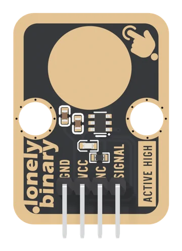
| Wires to your board | 3 of the 4: GND, VCC and SIGNAL. NC is connected to nothing on the board |
| Header | 4-pin right-angle male, 2.54 mm pitch: GND, VCC, NC, SIGNAL, with GND on the square pad |
| Board | 22.4 × 30.4 mm, two 4.8 mm mounting holes 16 mm apart. The front prints ACTIVE HIGH, the back DETECTS HUMAN TOUCH |
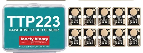
| The 12-pack | 12 boards in a hinged storage case |
What it does
A button with nothing to press. The gold disc on the front is the sensor: a TTP223 chip beside it measures the pad's capacitance many times a second, and a finger near the pad adds a few picofarads. SIGNAL goes HIGH while the finger is there and LOW when it leaves, and a red LED on SIGNAL lights with it.
Nothing moves, so nothing wears and nothing bounces, and because the pad's field passes through plastic and glass it works from behind a sealed panel with no hole cut in it.
The boxes
The TK43 is one block of the TinkerBlock kits. The 12-pack is twelve of the same board in a hinged case, for a project that wants several touch points.
Two things to know before wiring
- VCC is the level SIGNAL reaches. SIGNAL is the chip's own push-pull output, driven from VCC. So VCC goes to your board's logic supply: 3V3 beside an ESP32, an ESP32-S3 or a Pico, 5V beside an Uno. 5V beside a 3.3 V board puts 5 V on its pin at every touch.
- Leave the pad alone at power-up. For about half a second the chip learns what the pad reads with nothing on it. A finger there becomes the baseline, and later touches may be missed until it relearns.
Wiring, in four lines
- GND to your board's GND.
- VCC to 3V3 on an ESP32, ESP32-S3 or Pico; 5V on an Uno.
- SIGNAL to GPIO 4 on an ESP32-S3, GPIO 25 on an ESP32, D2 on an Uno,
GP15 on a Pico. Set the pin to
INPUT. - NC to nothing: it is connected to nothing on the board.
Then digitalRead(pin) is HIGH while the pad is touched.
Where to start
The handbook below is nine short articles, each with a working figure. The first touch is the whole build in three wires and a few lines, and VCC sets the HIGH is the page about the one wire that matters.
For how it works, read a finger is a capacitor and the first half second. For a touch that switches something on and off, a touch that latches. If a touch does nothing, when a touch does nothing.
When it doesn’t work
- Where is the jumper for toggle mode?
- This board does not have one. The chip's two option pins are soldered to GND in the copper, which selects momentary, active-high output and nothing else. Tutorials that bridge a pad on the back are describing a different TTP223 board. Toggle is a few lines in the sketch: flip a variable each time SIGNAL goes from LOW to HIGH.
- Should VCC go to 3V3 or 5V?
- To the voltage your board's pins run at. SIGNAL is the chip's own output, driven from VCC, so touched it sits at about VCC. That makes it 3V3 beside an ESP32, an ESP32-S3 or a Pico, and 5V beside an Uno. The chip runs on anything from 2.0 to 5.5 V.
- It never triggers.
- Look at the red LED while you touch the pad. Dark means power or the pad: check VCC and GND from the square pad, then power-cycle with your hand clear, because the chip learns the pad in its first half second. Lit means the chip saw you and the fault is the wire or the pin number: SIGNAL is the fourth pin, and the third, NC, goes nowhere.
- It stays HIGH after I let go.
- Something is still on or near the pad: a wire across it, a hand on the case. This chip never times out a long touch, so it holds HIGH until the thing moves. Clear the area and power-cycle.
- Can I mount it behind a panel?
- Yes, that is the point of it. The panel must have no metal in it, metallic paint included, and thinner is keener. Tontek does not publish a maximum thickness for this chip, so try the panel you intend to use.
- Do the 12-pack's boards come with the header soldered?
- The 12-pack's listing photograph shows the boards with bare holes, and the TinkerBlock kits' boards with the right-angle header fitted. Go by what is in your box; if the holes are bare, a strip of 2.54 mm header pins solders in.