Specifications
| Type | Three-LED output block, active high, one pin per light |
|---|---|
| LEDs | Red, yellow and green, 0805 surface-mount, stacked red on top |
| Resistors | 1 kΩ each, one per LED, between its cathode and GND. Printed 1001 |
| Current | About 3.1 mA for red and yellow and 2.3 mA for green from a 5 V pin; about 1.4 and 0.6 mA from 3.3 V. Worked out from the datasheets, not measured |
| Pins to wire | 4 of the 6: GND, RED, YELLOW and GREEN. The two NC pins are connected to nothing on the board |
| Header | 6-pin right-angle male, 2.54 mm pitch: GND, NC, NC, RED, YELLOW, GREEN, with GND on the square pad |
| Supply | None of its own. Each signal pin powers its own LED, so brightness follows your board's logic voltage |
| Board | 22.4 × 30.4 mm, two 4.8 mm mounting holes 16 mm apart |
| In the box | 1 × TK03 block. It also ships inside the TinkerBlock kits |
What it is
Three LEDs, three resistors and a header. The LEDs are small surface-mount parts stacked red, yellow and green beside a traffic light drawn in the silkscreen. Each has its own 1 kΩ resistor and its own pin, and the three share nothing but GND.
It is active high. Set a colour's pin HIGH and that light comes on, LOW and it goes out. The back of the board says so: each GPIO controls one light, HIGH turns on, LOW turns off.
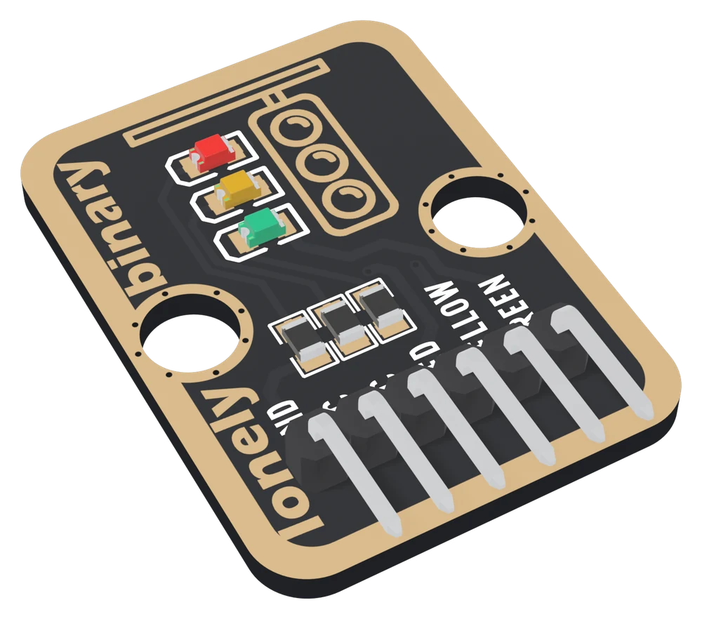
Nothing on the board stops two lights showing at once, the way a real signal's controller would. The sequence lives entirely in your sketch, which is what makes this block the natural first lesson in a program that remembers what it is doing.
Three lights, three currents
There is no supply pin: each signal pin powers its own LED. The green takes about 2.7 V before it conducts and the red and yellow about 1.9 V, so the green gets less of what is left:
| Your board | Pin voltage | Red | Yellow | Green |
|---|---|---|---|---|
| Arduino Uno | 5 V | about 3.1 mA | about 3.1 mA | about 2.3 mA |
| ESP32, ESP32-S3, Pico | 3.3 V | about 1.4 mA | about 1.4 mA | about 0.6 mA |
All of it is well within what any of these boards' pins may supply. The currents are worked out from the three LED datasheets, which give ranges, not measured on a board.
Which pin is which
LEDs up, header at the bottom, reading left to right:
| GND | to your board's GND | the square pad: count from here |
| NC | nothing | not connected on the board |
| NC | nothing | not connected on the board |
| RED | to a digital pin | HIGH lights red |
| YELLOW | to a digital pin | HIGH lights yellow |
| GREEN | to a digital pin | HIGH lights green |
The back prints TK03 TRAFFIC LIGHT and what the pins do instead of their names. Turned over, the square pad is on the right, and it is still GND.
Wiring, in four lines
- GND to your board's GND.
- RED to D9 on an Uno, GPIO 25 on an ESP32, GPIO 4 on an ESP32-S3, or GP13 on a Pico.
- YELLOW to D10, GPIO 26, GPIO 5 or GP14.
- GREEN to D11, GPIO 27, GPIO 6 on the S3, or GP15.
Leave both NC pins unconnected. No resistor to add, no library to install.
Example
// GPIO numbers. Uno: 9, 10, 11. ESP32: 25, 26, 27. ESP32-S3: 4, 5, 6.
// Pico: 13, 14, 15.
const int RED_PIN = 4;
const int YELLOW_PIN = 5;
const int GREEN_PIN = 6;

// Set all three at once, so no step can leave a light on by mistake.
void show(bool red, bool yellow, bool green) {
  digitalWrite(RED_PIN, red ? HIGH : LOW);
  digitalWrite(YELLOW_PIN, yellow ? HIGH : LOW);
  digitalWrite(GREEN_PIN, green ? HIGH : LOW);
}

void setup() {
  pinMode(RED_PIN, OUTPUT);
  pinMode(YELLOW_PIN, OUTPUT);
  pinMode(GREEN_PIN, OUTPUT);
}

void loop() {
  show(HIGH, LOW, LOW);   // red
  delay(5000);
  show(LOW, LOW, HIGH);   // green
  delay(5000);
  show(LOW, HIGH, LOW);   // yellow
  delay(2000);
}from machine import Pin
import time
# GPIO numbers. ESP32: 25, 26, 27. ESP32-S3: 4, 5, 6. Pico: 13, 14, 15.
red = Pin(4, Pin.OUT, value=0)
yellow = Pin(5, Pin.OUT, value=0)
green = Pin(6, Pin.OUT, value=0)
def show(r, y, g):
red.value(r)
yellow.value(y)
green.value(g)
while True:
show(1, 0, 0) # red
time.sleep(5)
show(0, 0, 1) # green
time.sleep(5)
show(0, 1, 0) # yellow
time.sleep(2)This is the plain red, green, yellow cycle many countries use. The UK, among others, shows red and yellow together before green; the handbook adds it as one row of a table.
Where to start
The handbook below is eight short articles, each with a working figure. The lamp test is the wiring in four wires and a sketch that proves it.
If you only read one, read a sketch that remembers. The example above waits for seconds at a time and notices nothing while it does; that article rewrites it so it never waits.
And if the green looks dim on your ESP32, why the green is different works out why that is normal.
When it doesn’t work
- One light never comes on.
- Two lights working proves GND and the block, so it is that colour's own wire or its own line of code. The number in the sketch is the GPIO number printed beside the pin on your board, not its position along the header, and every pin needs its own pinMode. Run the lamp test sketch: it names each colour as it lights it.
- Why is the green dimmer on my ESP32?
- The green LED takes about 2.7 V before it conducts, against about 1.9 V for the red and yellow, so a 3.3 V pin leaves it much less for its resistor: about 0.6 mA against 1.4 mA. It is normal. From a 5 V board the difference is much smaller, and the green's datasheet rates it bright at small currents.
- Do I need to add resistors?
- No. Each LED already has its own 1 kΩ resistor on the board, between the LED and GND, and it keeps the current well inside what any common board's pin may supply.
- Two lights are on at once.
- Nothing on the board prevents it: each pin lights its own LED whenever it is HIGH. The sketch left one on. Set all three pins in every step, even the ones that do not change, and it cannot happen.
- What are the two NC pins for?
- Nothing on this board. They are in no net at all. They keep the header's first positions the same as every other TinkerBlock block's, and this block needs only four of its six pins.
- The sequence stops responding to anything else.
- A sketch built from delay() is deaf while it waits, and a traffic light waits for seconds. Keep the current phase in a variable and compare millis() with the time it started instead. The handbook below rewrites the sequence that way.